 bkaii.com.vn
BKAII - Thiết bị truyền thông TỐT nhất với giá CẠNH TRANH nhất!
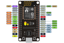
NodeMCU ESP32 OLED Wifi BLE
Giá: Liên hệ
Thông số kỹ thuật:
CPU: Xtensa Dual-Core 32-bit LX6 microprocessor, operating at 160 ...
NODEMCU - ESP8266 ESP12E
Giá: Liên hệ
NodeMCU ESP8266 - CP2102 dùng chip Wifi SoC ESP8266 có GPIO, PWM, I2C, 1-wire, ADC. Đ...
NANO32 esp32 IoT Development Board
Giá: Liên hệ
NANO32 được trang bị chip ESP32 dual core, tích hợp WiFi SoC và dual mode Blue...
MTCDTIP-LVW2-266A-915 GATEWAY LORA LTE ETHERNET USB
Giá: Liên hệ
Product Attributes
Categories
Networking Solutions
Gateways, Routers
Manuf...
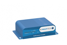
MTCDTIP-266A-915 GATEWAY LORA ETHERNET USB
Giá: Liên hệ
Product Attributes
Categories
Networking Solutions
Gateways, Routers
Manufac...
MTCDT-246A-915-US-EU-GB AEP PROGRAMMABLE GATEWAY W/MTAC
Giá: Liên hệ
Product Attributes
Categories
Networking Solutions
Gateways, Routers
Manufac...
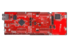
MSP-EXP432E401Y SimpleLink™ Ethernet MSP432E401Y MCU LaunchPad™ Development Kit
Giá: Liên hệ
The SimpleLink™ Ethernet MSP432E401Y microcontroller LaunchPad™ Development Kit is an in...
Module Wifi ESP8266 ESP-07S
Giá: Liên hệ
ESP-07S WiFi module, là phiên bản nâng cấp từ ESP-07 được phát t...
Module Wifi BLE ESP32 Mini Kit MH-ET LIVE
Giá: Liên hệ
ESP-32 ESP-32S Development Board WiFi Bluetooth Ultra-Low Power Consumption Dual Cores ESP32 Board
...
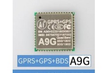
Module GSM GPRS GPS BD A9G
Giá: Liên hệ
Mạch GSM GPRS GPS BDS A9G sử dụng Module A9G của AI-Thinker đi kèm Anten GSM V...
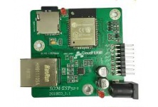
Module ESP32 SOM-ESP32-1
Giá: Liên hệ
Thông số kỹ thuật:
Tích hợp ESP-WROOM-032 chính hãng Espressif...
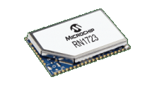
Microchip Wifi Module RN1723-I/RM100
Giá: Liên hệ
The RN1723 is a small form factor, ultra-low power embedded TCP/IP/UDP Wi-Fi module measuring only 2...
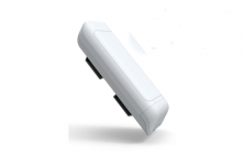
LoRa Semi-Outdoor Micro Gateway
Giá: Liên hệ
LoRa Semi-Outdoor Micro Gateway
Compliance to LoRaWAN 1.0.2
Up to 16 concurrent channels for L...
LoRa Outdoor Micro Gateway
Giá: Liên hệ
LoRa Outdoor Micro Gateway
Compliance to LoRaWAN 1.0.2
Up to 16 concurrent channels for LoRa tra...
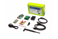
LoRa LoRaWAN Gateway - 868MHz Kit with Raspberry Pi 3
Giá: Liên hệ
LoRa is a perfect long-range wireless solution to create low-power, wide area networks.So far we h...
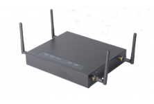
LoRa Indoor Pico Gateway
Giá: Liên hệ
LoRa Indoor Pico Gateway
Compliance to LoRaWAN 1.0.2
Up to 16 concurrent channels for LoRa tra...
LoRa Indoor Femto Gateway
Giá: Liên hệ
LoRa Indoor Femto Gateway
Compliance to LoRaWAN 1.0.2
Up to 8 concurrent channels for LoRa trans...
LIS33DE Accelerometer Sensor Development Kit
Giá: Liên hệ
Specifications
EU RoHS
Supplier Unconfirmed
Type
Development Kit
Supported Device
...
LinkIt Smart 7688 SKU 102110018
Giá: Liên hệ
The Linklt Smart 7688 development platform offers two developments boards:
Linklt Smart 7688: M...
LBWB1ZZ1AD-812 Wifi Module Murata
Giá: Liên hệ
Specifications
EU RoHS
Supplier Unconfirmed
Technology
IEEE 802.11b/g/n
Style
Modu...

